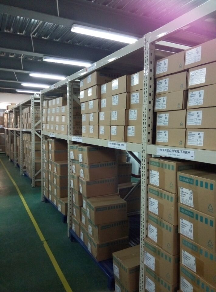
产品介绍
西门子6AV6648-0BE11-3AX0参数型号及价格SMART 1000IE10.2 英寸宽屏 采购
西门子6AV6648-0BE11-3AX0参数型号及价格SMART 1000IE10.2 英寸宽屏西门子6AV6648-0BE11-3AX0参数型号及价格SMART 1000IE10.2 英寸宽屏西门子6AV6648-0BE11-3AX0参数型号及价格SMART 1000IE10.2 英寸宽屏
以下为SMART系列PLC 所有订货号:
6ES7 288-1SR20-0AA0
6ES7 288-1SR40-0AA0
6ES7 288-1ST40-0AA0
6ES7 288-1SR60-0AA0
6ES7 288-1ST60-0AA0
6ES7 288-1CR40-0AA0
6ES7 288-2DE08-0AA0
6ES7 288-2DR08-0AA0
6ES7 288-2DT08-0AA0
6ES7 288-2DR16-0AA0
6ES7 288-2DT16-0AA0
6ES7 288-2DR32-0AA0
6ES7 288-2DT32-0AA0
6ES7 288-3AE04-0AA0
6ES7 288-3AQ02-0AA0
6ES7 288-3AM06-0AA0
6ES7 288-3AR02-0AA0
6ES7 288-5CM01-0AA0
6ES7 288-5DT04-0AA0
6ES7 288-5AQ01-0AA0
型号 CPU SR20 AC/DC/RLY
订货号(MLFB) 6ES7 288-1SR20-0AA0
西门子PLC系列介绍:
S7-200 CN PLC 实用于各行各业,各种场所中的检测、监测及掌握的主动化。S7-200 CN 系列的壮大功用使其无论在独立运行中,或相连成网络皆能完成庞杂掌握功用。因而S7-200CN 系列具备较高的性能价钱比。
相关图形:
SIMATIC S7-300 一种通用型PLC,能适合自动化工程中的各种应用场合,尤其是在生产制造工程中的应用。模块化、无排风扇结构、易于实现分布式的配置、以及用户易于掌握等特点,使得S7-300 PLC在以下工业部门中实施各种控制任务时,成为一种既经济又切合实际的解决方案:
相关图形:
在制造自动化和过程自动化中,对一切中、高端的运用来说,SIMATIC S7-400 都是功用强大的PLC。 S7-400 PLC分为规范型和容错型(可配置成故障安全型) 两种。强大的体系功用和便捷的用户界面使得SIMATIC S7-400 成为各种自动化功用的技巧和经济性处理计划
相关图形:
LOGO!-通用逻辑控制模块填补了继电器与PLC之间的技术空间,目前已发展成为模块化的标准组件产品,而且其性能亦更为优越!通过集成的8种基本功能和26种特殊功能,LOGO!可以代替数以百计的开关设备,从时间继电器一直到接触器。新的模块化LOGO!能够节省控制柜的空间,需要的附件更少从而进一步降低库存量,并且根据您的任务需求,可随时进行灵活扩展。因此,LOGO!不仅节约成本费用,而且能缩短工程时间达70%。LOGO!安装方便,几乎不需任何接线,编程也较其简单。更加值得一提的是,LOGO!有很好的抗振性和很高的电磁兼容性(EMC),完全符合工业标准,能够应用于各种气候条件。LOGO!达到了B级无线电干扰抑制指标并通过了所有必需的国际认证,因此,LOGO!得以在全世界范围内广泛应用!
相关图形:
西门子simatic家族新品——S7-1500PLC的特性剖析
西门子S7-1500PLC作为西门子S7系列PLC家族中的新品,相信很多工控朋友都没有使用过甚至都没有太多的了解,对此,西门子方专门进行了产品推广会针对S7-1500进行介绍,康斯达作为西门子系统集成商参加推广会。
下面小编根据推广会将S7-1500的特性整理成下面几点,S7-1500主要特性有:
1、所有模块都支持热插拔
2、多可以扩展31个模块,但是所有的扩展模块必须在一排,因为1500还没有推出基架扩展模块
3、1500所有系类的CPU至少附带一个PROFINET网口
4、1500的前连接器都是40针的
5、扩展模块分为标准型和经济型两类:1、标准型35mm宽度,自带前连接器,2、经济型25mm宽度 需要另购买连接器
6、1500的AI模块无量程卡(针对S7-300的7KF02)
7、500进行RS485通讯*要硬件狗,只需模块即可(针对S7-300的CP340 CP341)
8、1500从站支持与ET200S
Short version with
LG ≤ 3 x DA v?≤ 30 m/s v?> 30 m/s
Long version with
LG > 3 x DA v?≤ 15 m/s v?> 15 m/s
Peripheral speed v in m/s
Coupling outer diameter DA in mm
Coupling speed n in rpm
Coupling length LG in mm
The following balancing standards must be observed:
?Subassemblies and coupling parts are designed with standard balancing quality.
?Fine balancing and microbalancing are available to order.
?Higher balancing qualities are provided on request, after technical clarification.
?Hub parts without finished bore are not balanced.
?FLUDEX couplings are subject to special balancing standards.
?ARPEX couplings in standard balancing quality are unbalanced. The balancing quality of standard balancing is nearly always adhered to by steel components which are machined all round and precisely guided adapters.
?The number of balancing levels (single- or two-level balancing) is specified by FLENDER.
?Unless otherwise requested, the unit is balanced in accordance with the half parallel key standard. Balancing in accordance with the full parallel key standard must be specified in the product code.
Shaft-hub connections
The bore and the shaft-hub connection of the coupling is determined by the design of the machine shaft. In the case of IEC standard motors the shaft diameters and parallel key connections are specified in accordance with DIN?EN?50347. For diesel motors the flywheel connections are frequently specified in accordance with SAE?J620d or DIN?6288. Besides the very widely used connection of shaft and hub with parallel keys to?DIN 6885 and cylindrically bored hubs, couplings with taper clamping bushes, clamping sets, shrink-fit connections and splines to DIN?5480 are common.
The form strength of the shaft/hub connection can only be demonstrated when shaft dimensions and details of the connection are available. The coupling torques specified in the tables of performance data of the coupling series do not apply to the shaft-hub connection unrestrictedly.
In the case of the shaft-hub connection with parallel key the coupling hub must be axially secured e.g. with a set screw or end plate. The parallel key must be secured against axial displacement in the machine shaft.
All FLENDER couplings with a finished bore and parallel keyway are designed with a set screw. The exceptions are some couplings of the FLUDEX series, in which end plates are used. During assembly taper clamping bushes are frictionally connected to the machine shaft.
Assembly
Assembly, start-up, maintenance and servicing of the coupling are described in the operating instructions.
Contact protection
Couplings are rotating components which can pose a risk to the environment. FLENDER in the operating instructions prescribes fitting couplings with a suitable contact guard, also called a coupling guard. The contact guard must provide a firm cover to protect against contact with the rotating coupling. The coupling must also be protected against blows from objects striking it. The coupling guard must enable the coupling to be adequately ventilated. The following guidelines give information on designing the contact guard: 2006/42/EC EC Machinery Directive; EN?13463-1 Section?13.3.2.1; EN?13463-1 Section?7.4; EN?13463-1 Section?8.1.
Maintenance
All-steel membrane couplings of the ARPEX series require no maintenance. If the operating and mounting conditions have been adhered to, only regular visual inspection is required.
Elastomer elements, elastomer seals and lubricants are subject to wear through ageing and loads. To avoid damage to the coupling or failure of the drive, the ZAPEX, N-EUPEX, N-EUPEX DS, RUPEX, BIPEX, ELPEX, ELPEX-S, ELPEX-B and FLUDEX series must be maintained in accordance with the operating instructions.?
On gear couplings the lubricant must be changed at regular intervals.
On flexible or highly flexible couplings the torsional backlash or the torsion angle must be checked at regular intervals under load. If a limit value is exceeded the elastomer element must be replaced. It is very important to maintain couplings which are operated in a potentially explosive environment, as couplings which are not maintained can become ignition sources.
Corrosion protection
Depending on the environmental conditions, suitable corrosion protection must be specified for the coupling. Unless otherwise specified in the order, steel and cast iron surfaces are shipped with a simple preservative.
Ambient conditions
Because of the environment the coupling has to meet a large number of additional requirements. Couplings must be as suitable for use in a potentially explosive environment as for use at a high or low ambient temperature. The environment may be defined as chemically aggressive or be subject to laboratory conditions or requirements of food manufacture.
ATEX and EC Machinery Directive
Wherever a potentially explosive environment cannot be ruled out the machinery used must meet special conditions in order to prevent the outbreak of fire as far as possible. Within the European Union, Directive 94/9/EC applies to these applications. This directive, also called ATEX 95, harmonizes the individual states' legal requirements for explosion prevention and clearly defines the procedure for checking and circulating machines and parts.?
Whether or not a machine is used in a potentially explosive environment, the manufacturer is required under EC Machinery Directive 98/37/EC to assess and as far as possible prevent hazards which may arise from his product.
The operator has an obligation to ascertain whether an environment is potentially explosive. Details of this are laid down in Directive 1999/92/EC, also known as ATEX?137.
The manufacturer is responsible for ensuring that the product is safe as defined in the EC Machinery Directive and conforms to Directive 94/9/EC, if the EX requirement is specified by the operator.
The drive train mostly comprises individual pieces of equipment which are put together to form a subassembly. If the individual pieces of equipment, such as the motor, coupling, gear unit or driven machine, conform to Directive 94/9/EC, the manufacturer of the overall unit can limit the risk assessment to the additional hazards which arise from the combination of different individual pieces of equipment. The hazards which can arise from the individual pieces of equipment are assessed by the relevant suppliers.
All FLENDER couplings conform to the requirements of the EC Machinery Directive 98/37/EC.
The coupling series suitable for use in potentially explosive environments are marked EX.
Coupling behavior during overload conditions
Behavior under overload where the torque is considerably above the limits of use of the coupling concerned is determined by the engineering design of the coupling series.
The ZAPEX, ARPEX, N-EUPEX, RUPEX and BIPEX coupling series can withstand overloads until the breakage of metal parts. These coupling series are designated as fail-safe. Coupling types which can withstand overload, i.e. fail-safe types, are used e.g. in crane systems.
The N-EUPEX DS, ELPEX-B, ELPEX-S and ELPEX coupling series throw overload. The elastomer element of these couplings is irreparably damaged without damage to metal parts when subjected to excessive overload. These coupling series are designated as non-fail-safe. The types that fail can be fitted with a fail-safe device. This component enables emergency operation, even after the rubber element of the coupling has been irreparably damaged.
The fluid couplings of the FLUDEX series withstand a load for a short time. Persistent overload causes the FLUDEX coupling to heat up beyond limits, causing the fuse to operate and so emptying the coupling and interrupting the torque transmission.
Torsional and bending vibrations
On drives which are prone to torsional and bending vibrations, calculations such as natural frequency calculations, torsional vibration simulations or bending vibration calculations are necessary.
The drive train may, depending on complexity, be regarded as a two-mass vibration-generating system or N-mass vibration-generating system. The vibration-generating masses are defined by the rotating bodies and the couplings by the coupling stiffnesses and shaft stiffnesses. The effect of torsional vibration excitations on the behavior of the system is calculated.
Torsional vibration excitations may occur during the starting of an asynchronous motor, during a motor short circuit or in diesel engine drives. Bending vibrations may be critical, if the coupling is insufficiently balanced and/or at an operating speed close to the critical speed.
The details needed for calculating torsional vibration
?Dynamic torsional stiffness
?Damping (specification of the damping coefficient ψ or Lehr's damping D?=?ψ/4π).
?Mass moment of inertia of the coupling halves are specified in the coupling catalog.
Standards
Machines
2006/42/EG EC Machinery Directive (formerly: 98/9/EC)
94/9/EG ATEX 95 Directive – Manufacturer – and ATEX Guideline to Directive 94/9/EC
1999/92/EG ATEX 137 Directive – Operator – and ATEX Guideline to Directive 199/92/EC
DIN?EN?13463 Non-electric equipment for use in potentially explosive areas
DIN?EN?1127 Potentially explosive atmospheres, explosion protection
Couplings
DIN?740 Elastic shaft couplings Part 1 and Part 2
VDI Guideline?2240 Shaft couplings - Systematic subdivision according to their properties VDI Technical Group Engineering Design 1971
API?610 Centrifugal Pumps for Petroleum, Chemical and Gas Industry Services
API?670 Machinery Protection System
API?671 Special Purpose Couplings for Petroleum, Chemical and Gas Industry Services
Balancing
DIN?ISO?1940 Requirements for the balancing quality of rigid rotors
DIN?ISO?8821 Mechanical vibrations; standard governing?
the type of parallel key during balancing of shafts and composite parts
Shaft-hub connections
DIN?6885 Driver connections without taper action – parallel keys – keyways
SAE?J5620d Flywheels for industrial engines ...
DIN?6288 Internal-combustion piston engines Connection dimen sions and requirements for flywheels and flexible coupling
ASME?B17.1 Keys and keyseats
DIN?EN?50347 General-purpose three-phase induction motors with standard dimensions and output data
BS 46-1:1958 Keys and keyways and taper pins Specification
Formula symbols
Key to the formula symbols
Name Symbol Unit Explanation
Torsional stiffness, dynamic CTdyn Nm/rad For calculating torsional vibration
Excitation frequency ferr Hz Excitation frequency of motor or driven machine
Moment of inertia J kgm2 Moment of inertia of coupling sides 1 and 2
Axial misalignment ΔKa mm Axial misalignment of the coupling halves
Radial misalignment ΔKr mm Radial misalignment of the coupling halves
Angular misalignment ΔKw ° Angular misalignment of the coupling halves
Service factor FB ? Factor expressing the real coupling load as a ratio of the nominal coupling load
Frequency factor FF ? Factor expressing the frequency dependence of the fatigue torque load
Temperature factor FT ? Factor taking into account the reduction in strength of flexible rubber materials at a higher temperature
Weight m kg Weight of the coupling
Rated speed nN rpm Coupling speed
Maximum coupling speed nKmax rpm Maximum permissible coupling speed
Rated power PN kW Rated output on the coupling, usually the output of the driven machine
Rated torque TN Nm Nominal torque as nominal load on the coupling
Alternating torque TW Nm Amplitude of the dynamic coupling load
Maximum torque Tmax Nm More frequently occurring maximum load, e.g. during starting
Overload torque TOL Nm Very infrequently occurring maximum load, e.g. during short circuit or blocking conditions
Nominal coupling torque TKN Nm Torque which can be transmitted as static torque by the coupling over the period of use.
Maximum coupling torque TKmax Nm Torque which can be frequently transmitted (up to 25 times an hour) as maximum torque by the coupling.
Coupling overload torque TKOL Nm Torque which can very infrequently be transmitted as maximum torque by the coupling.
Alternating cou pling torque TKW Nm Torque amplitude which can be transmitted by the coupling as dynamic torque at a frequency of 10 Hz over the period of use.
Resonance factor VR ? Factor specifying the torque increase at resonance
Temperature Ta °C Ambient temperature of the coupling in operation
Damping coefficient Ψ Psi Damping parameter
欢迎来到上海西邑电气技术有限公司网站, 具体地址是上海松江新桥鼎源路时尚创意园61号五楼,联系人是曾海清。
联系电话是021-80185250,联系手机是15601981291, 主要经营西门子全系列特价销售。
单位注册资金单位注册资金人民币 100 - 250 万元。
显示更多
产品参数
- 价格88.00 元/件
- 数量5000.00 件
- 产品规格6AV6648-0BE11-3AX0
- 包装说明全新原装
- 发货地址上海上海
- 行业电气 工控电器 DCS/PLC系统
- 查看人数141
- 信息编号97929379
- 公司编号14813481
- 相关产品 smart
联系方式
- 公司上海西邑电气技术有限公司
- 联系人曾海清女士(销售经理)
- 电话021-80185250
- 手机15601981291
- 邮编201600
- 地址上海 松江 新桥 鼎源路时尚创意园61号五楼
- 商铺上海西邑电气技术有限公司商铺
相关分类 更多
收起
相关地区
热门地区全部分类
最新产品
